I think, this book is a starting point when you would like to learn the Embedded Linux for a Microcontroller, also the Real Time Operating System.
Source: http://oreilly.com/emails/press/9780596100797.html
Buy Linux Kernel in a Nutshell
Resources and Tutorials,8051, Software and Tools, C Programming, Chip Architecture, Hardware, Interfacing, sdcc, ARM, Compilers, Simulator, PIC, Robotics, Servo Motor, 8052, Analog-to-Digital Books, EEPROMs. I²C, LCD, Projects, RTOS Real Time Clock, Sensors
The eclipseSDCC project aims to provide full support for the open source Small Device C Compiler (SDCC) from within the eclipse/CDT development environment. This allows embedded 'C' applications for 8051 and Z80 devices to be developed using the fully featured eclipse IDE. EclipseSDCC supports CDT managed make projects. In managed make projects CDT manages the build process by creating and maintaining the underlaying makefiles. CDT keeps track of source dependencies and can automatically rebuild the target when needed.
To install (for Windows)
 Related Links
The AT89C51RE2 is available in 44-pin PLCC and VQFP packages at $4.80 for 10,000 units.
Atmel offers the AT89STK-11, a starter kit for $99, to evaluate the AT89C51RE2; designers can either run the demonstration program or their own application. A new low-cost on-chip debug tool, AT89OCD-01 will be available by the end of November 2006.
$s51 -t 89c51r
0>conf
ucsim version 0.5.4
Type of microcontroller: 89C51R CMOS
Controller has 13 hardware element(s).
timer0[0]
timer1[1]
uart[0]
port[0]
port[1]
port[2]
port[3]
irq[0]
_51_dummy[0]
timer2[2]
wdt[0]
pca[0]
_89c51r_dummy[0]
$tar -xvfz sdcc-src-xxx-xxx.tar.bz2If it succeed, you should have these directories:
$cd sdcc
$./configure --prefix=/usr
$make
$make install
#include <8051.h>
void min() {
unsigned char var_1;
var_1 = 0xFF;
}
$sdcc test.cand I found the test.ihx file in that directory which is the expected output.
MCS51 family is simulated by s51
AVR family is simulated by savr
Z80 processor is simulated by sz80
XA family is simulated by sxa
HC08 processor is simulated by shc08
The program can be started using following command:
C:\> s51 [input file]
Parameter is optional. If it specified it must be the name of an Intel hex file.The P89LPC9381 is a single-chip microcontroller, available in low-cost packages, based on a high performance processor architecture that executes instructions in two to four clocks, six times the rate of standard 80C51 devices. Many system-level functions have been incorporated into the P89LPC9381 in order to reduce component count, board space, and system cost.
 GP2Y0A21YK is General Purpose Type Distance Measuring Sensors from Sharp. (see the product page). Sharp Infrared (IR) radiation Distance Measuring Sensor use Infrared signal to measure object distance from 10 to 80 cm with analog output.
Features
Applications
The output of this sensor is analog therefore it need Analog to Digital Converter (ADC) to interface the 8051. I use ads7841 as ADC (see this article).
The graph of Analog voltage output versus distance to reflective object are shown in Fig.1. When I plot Analog voltage output versus inverse number distance, I found the linear relation shown in Fig.2.
Fig. 2 Analog voltage output (V) versus inverse number distance (1/cm).
The linear equation is y = 20.99x + 0.19, where y is voltage output and x invert distance. Notice that the voltage output I can trust are about 0.4 to 2.8 V.
This is an example code how to interface the distance sensor to 8051. I use SDCC as C Compiler.
#include <8051.h>
#include "ads7841.h"void main()
{
float x,y; // Distance and Analog voltage output
y = analog(0); // Read volt out if the sensor connect to channel 0 of ADS7841
y = 0.00122*y; // Convert BCD to DEC by multiply voltage by 5/4096
if ( (y > 0.4) && (y < 2.8) ) {
x = (y-0.19)/20.99; // Solve the linear equation
x = 1/x; // Inverse back get distance in cm.
}
}

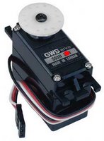
Servos are DC motors with built in gearing and feedback control loop circuitry. And no motor drivers required. They are extremely popular with robot, RC plane, and RC boat builders. Most servo motors can rotate about 90 to 180 degrees. Some rotate through a full 360 degrees or more.
However, servos are unable to continually rotate, meaning they can't be used for driving wheels, unless they are modified (how to modify), but their precision positioning makes them ideal for robot legs and arms, rack and pinion steering, and sensor scanners to name a few. Since servos are fully self contained, the velocity and angle control loops are very easy to impliment, while prices remain very affordable. To use a servo, simply connect the black wire to ground, the red to a 4.8-6V source, and the yellow/white wire to a signal generator (such as from your microcontroller). Vary the square wave pulse width from 1-2 ms and your servo is now position/velocity controlled.
PWM
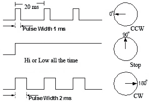
Pulse width modulation (PWM) is a powerful technique for controlling analog circuits with a processor's digital outputs. PWM is employed in a wide variety of applications, ranging from measurement and communications to power control and conversion. The general concept is to simply send an ordinary logic square wave to your servo at a specific wave length, and your servo goes to a particular angle (or velocity if your servo is modified). The wavelength directly maps to servo angle.The standard time vs angle is represented in this chart:
 Figure: Pulse for controlling a Servo motor
Programmable Counter Array (PCA)
8051 Pulse width modulator mode
All of the PCA modules can be used as PWM outputs. Output frequency depends on the source for the PCA timer. All of the modules will have the same frequency of output because they all share one and only PCA timer. The duty cycle of each module is independently variable using the module's capture register CCAPnL.When the value of the PCA CL SFR is less than the value in the module's CCAPnL SFR the output will be low, when it is equal to or greater than the output will be high. When CL overflows from FF to 00, CCAPnL is reloaded with the value in CCAPnH. this allows updating the PWM without glitches. The PWM and ECOM bits in the module's CCAPMn register must be set to enable the PWM mode. For more details see P89V51RD2 datasheet.
This is an example how to control servos with 8051 by using PWM. The schematic is shown below. I use P1.4 (CEX1) to control the left servo and P1.2 (CEX2) to control the right servo. Here, I use GWS servo motor model S03T STD. I need three states of duty cycle:
Calculation for duty cycle (for XTAL 18.432 MHz with 6 Clock/Machine cycle)
Datasheet
- P89V51RD2 [pdf]
Source Code (For SDCC)
- pwm_servos.h
- test_servos.c
Related Links
- What is a Servo?
- Tutorial on how to modify a servo for full 360 degree rotation
- Servo Tutorial for Robotics
- Pulse-width modulation (Wiki)
- Introduction to Pulse Width Modulation (PWM)

This device is capable of both random and sequential reads up to the 512K boundary. Functional address lines allow up to eight devices on the same bus, for up to 4 Mbit address space.
This is an example how to interface 24XXX EEPROMs with 8051. I use SDCC as C Compiler. My schematic is shown below.
Schematic: 8051 interface to 24XXX EEPROMs
Datasheet
- 24LC512 [pdf]
Source Code (For SDCC)
- 24xx512.h
- test_eeprom.c
Related Links
-24LC512 Products Page
-Interfacing I2C EEPROM (24LC256) with MCS-51 (KEIL C51)

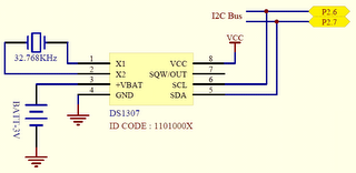
This is an example how to interface DS1307 with 8051. I use SDCC as C Compiler. My schematic is shown below.

Schematic: 8051 interface to DS1307
Datasheet
- DS1307 [pdf]
Source Code (For SDCC)
- ds1307.h
- test_ds1307.c
Note: require lcd.h and i2c.h
Related Links
- DS1307 Products Page
- Interfacing I2C RTC (DS1307) with MCS-51 (KEIL C51)
Three speed modes are specified: Standard; 100kbps [Bits per Second], Fast mode; 400kbps, High speed mode 3.4Mbps. I2C, due to its two-wire nature (one clock, one data) can only communicate half-duplex. The maximum bus capacitance is 400pF, which sets the maximum number of devices on the bus and the maximum line length.
The interface uses 8 bit long bytes, MSB (Most Significant Bit) first, with each device having a unique address. Any device may be a Transmitter or Receiver, and a Master or Slave. The Slave is any device addressed by the Master. A system may have more than one Master, although only one may me active at any time.
Data and clock are sent from the Master: valid while the clock line is high. The link may have multiple Masters and Slaves on the bus, but only one Master may be active at any one time. Slaves may receive or transmit data to the master.
This is an example how to interface I²C with 8051. I use SDCC as C Compiler. My schematic is shown below. I set P2.6 as SCL and P2.7 as SDA.

Datasheet
I²C-Bus Specification [pdf]
Source Code (For SDCC)
- i2c.h
Note: see DS1307 and 24LC512 for applications
Related Links
- Philips I²C Bus
- I2C (Inter-Integrated Circuit) Bus Technical Overview and Frequently Asked Questions (FAQ)
- I²C Bus and Access Bus
- http://www.i2c-bus.org/

This is an example how to interface ADS7841 with 8051. I use SDCC as C Compiler. My schematic is shown below. I still do not convert to the real value so my variables are integer.
Datasheet
- ADS7841 [pdf]
Source Code (For SDCC)
- ads7841.h
- test_ads7841.c
Note: require lcd.h
Related Links
- ADS7841 Products Page


Source Code (For SDCC)
- lcd.h
- test_lcd.c
Related Links
- How to control a HD44780-based Character-LCD: The Industry Standard Character LCD
- Yet Another 8051-to-LCD Interface
- Interfacing: Converting 8-bit LCD communication to 4-bit
This page is an installation guide for someone who are interested in developing 8051 microcontrllor with C-language. All of tools I selected are freeware or opensource with no limitation of number of lines of your code.
Contents
1. Installing MIDE-51
MIDE-51 is freeware Integrated Development Environment (IDE) for MCS-51 microcontroller. The full package already comes with:
Assembler : ASEM-51 by W.W.Heinz (v1.3)
C compiler : SDCC: Small Device C Compiler (v2.5.4)
Simulator : TS Controls 8051 Emulator v1.0 evaluation (Owner : http://www.tscontrols.com was gone)
Simulator : JSIM-51 Simulator by Jens Altmann (v4.05)
Just downloads midepack0258.exe and executes this file, everything will setup completely.
Feature on MIDE-51:
However, if you would like to use the newer version of them, you can also install each package manualy. First, downloads only editor version of MIDE-51 ( MIDE51_0258.zip) and extracts it to any directory (C:\MIDE51). You should have C:\MIDE51\MIDE51.EXE. For others package, please follow these instructions.
2. Installing SDCC
SDCC is a Freeware, retargettable, optimizing ANSI - C compiler that targets the Intel 8051, Maxim 80DS390, Zilog Z80 and the Motorola 68HC08 based MCUs. Work is in progress on supporting the Microchip PIC16 and PIC18 series. The entire source code for the compiler is distributed under GPL.
To install the SDCC, download the latest version from http://sdcc.sourceforge.net/snap.php#Windows (currently v2.6.x). SDCC are available for several different operating systems. I am working on a PC running Microsoft Windows XP therefore I download the win32 self-executing SDCC install file
(sdcc-20060818-4339-setup.exe) and run the executable. By default, it will install all files to C:\Program Files\SDCC, you also can change to any directory.
When finishing installing the program, a prompt will appear asking to add the directory containing the program binaries to your PATH. I also recommend you to download the SDCC documentation (sdcc-doc-20060818-4339.zip), and extract it to your SDCC documentation directory (C:\Program Files\SDCC\doc).
3. Installing ASEM-51
ASEM-51 is a two-pass macro assembler for the Intel MCS-51 family of microcontrollers. It is running on the PC under MS-DOS, Windows and Linux. The ASEM-51 assembly language is based on the standard Intel syntax, and implements conditional assembly, macros, and include file processing. The assembler can output object code in Intel-HEX or Intel OMF-51 format as well as a detailed list file. The ASEM-51 package includes support for more than 180 8051 derivatives, a bootstrap program for MCS-51 target boards, and documentation in ASCII and HTML format. And it is free ...
The simplest way of installing ASEM-51 is copying all files of the package to your working directory, and enjoy the benefits of true plug-and-play compatibility!. Alternatively, I have set it up on Windows XP manually:
You can update MPU file by downloading http://plit.de/asem-51/mcufiles.zip.
4. Installing JSIM-51
JSIM-51 is a powerful software simulator for 8051 Microcontrollers and it's derivatives. The program simulates the processor kernel and some of the hardware functions. It was born due to all commercial products are too expensive for private users. It is free and opensource.
To install:
Extract all files i.e., jsim.exe, 8051.dll and 80320.dll to your directory (C:\Jsim51).
5. Installing FlashMagic ISP Software
Flash Magic is a free, powerful, feature-rich Windows application that allows easy programming of Philips Flash Microcontrollers. Its function is to download compiled HEX file to your (Philips) microcontroller.
Please download and install the current version of FlashMagic.exe here.
6. Configuration
To combine every things:
7. Test
Execute MIDE-51.exe and File-->New (Ctrl+N), edit this code
#include <p89v51rd2.h>Save to anyname.c and then Build (F9). You will found many files in the directory, one of them is .HEX file which can be downloaded to your MCU by using FlashMagic. Or, you can simulate it by using Jsim51, Build and Sim (Shift+Ctrl+F9).
unsigned char i;
void main() {
i=10;
}
Note: I tested on my P89V51RD2 MPU. Enjoy your 8051 microcontroller.
Related Links
Product Page: http://www.semiconductors.philips.com/
Data Sheet: P89V51RB2_RC2_RD2-03.pdf
Boot Loader: p89v_lv51rd2_bl_upd_v5.zip
FlashMagic ISP Software: http://www.esacademy.com/
SDCC : http://sdcc.sourceforge.net/
MIDE-51 : http://www.opcube.com/home.html
ASEM-51 : http://plit.de/asem-51/home.htm
JSIM-51 : http://home.arcor.de/jensaltmann/jsim-e.htm
SDCC is a Freeware, retargettable, optimizing ANSI - C compiler that targets the Intel 8051, Maxim 80DS390, Zilog Z80 and the Motorola 68HC08 based MCUs. Work is in progress on supporting the Microchip PIC16 and PIC18 series. AVR and gbz80 ports are no longer maintained. The entire source code for the compiler is distributed under GPL.
Some of the features include:
SDCC also comes with the source level debugger SDCDB, using the current version of Daniel's s51 simulator. (Currently not available on Win32 platforms).
SDCC was written by Sandeep Dutta and released under a GPL license. Since its initial release there have been numerous bug fixes and improvements. As of December 1999, the code was moved to SourceForge where all the "users turned developers" can access the same source tree. SDCC is constantly being updated with all the users' and developers' input.
SDCC Homepage
- http://sdcc.sourceforge.net/
I am using Philips P89V51RD2 as 8051 Microcontroller Unit (MCU). And I have been developing my code with Opensouce C Compiler SDCC. Please visit my Tools page for software preparation guides.
The P89V51RD2 is a 80C51 microcontroller with 64 kB Flash and 1024 bytes of data RAM. A key feature of the P89V51RD2 is its X2 mode option. The design engineer can choose to run the application with the conventional 80C51 clock rate (12 clocks per machine cycle) or select the X2 mode (6 clocks per machine cycle) to achieve twice the throughput at the same clock frequency. Another way to benefit from this feature is to keep the same performance by reducing the clock frequency by half, thus dramatically reducing the EMI.
The Flash program memory supports both parallel programming and in serial In-System Programming (ISP). Parallel programming mode offers gang-programming at high speed, reducing programming costs and time to market. ISP allows a device to be reprogrammed in the end product under software control. The capability to field/update the application firmware makes a wide range of applications possible.
The P89V51RD2 is also In-Application Programmable (IAP), allowing the Flash program memory to be reconfigured even while the application is running.
Features
The 8051 is an 8 bit microcontroller originally developed by Intel in
1980. It is the world's most popular microcontroller core, made by
many independent manufacturers (truly multi-sourced). There were 126
million 8051s (and variants) shipped in 1993!!
A typical 8051 contains:
One strong point of the 8051 is the way it handles interrupts.
Vectoring to fixed 8-byte areas is convenient and efficient. Most
interrupt routines are very short (or at least they should be), and
generally can fit into the 8-byte area. Of course if your interrupt
routine is longer, you can still jump to the appropriate routine from
within the 8 byte interrupt region.
The 8051 instruction set is optimized for the one-bit operations so
often desired in real-world, real-time control applications. The
boolean processor provides direct support for bit manipulation. This
leads to more efficient programs that need to deal with binary input
and output conditions inherent in digital-control problems. Bit
addressing can be used for test pin monitoring or program control
flags.
See full information from 8051 FAQ
- http://www.faqs.org/faqs/microcontroller-faq/8051/