Showing posts with label Interfacing. Show all posts

Friday, September 15, 2006

EEPROMs Interfacing


24LC512 is a 64K x 8 (512 Kbit) Serial Electrically Erasable PROM (EEPROMs), from Microchip Technology Inc. (see the product page). It has been developed for advanced, low-power applications such as personal communications and data acquisition. This device also has a page write capability of up to 128 bytes of data.

This device is capable of both random and sequential reads up to the 512K boundary. Functional address lines allow up to eight devices on the same bus, for up to 4 Mbit address space.

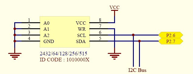
This is an example how to interface 24XXX EEPROMs with 8051. I use SDCC as C Compiler. My schematic is shown below.

Schematic: 8051 interface to 24XXX EEPROMs

Datasheet
- 24LC512 [pdf]

Source Code (For SDCC)
- 24xx512.h
- test_eeprom.c

Note: require lcd.h and i2c.h


Related Links
-24LC512 Products Page
-Interfacing I2C EEPROM (24LC256) with MCS-51 (KEIL C51)

Saturday, September 9, 2006

Real Time Clock Interfacing


DS1307, a 64 x 8, Serial, I2C Real-Time Clock, is a low-power, full binary-coded decimal (BCD) clock/calendar plus 56 bytes of NV SRAM. Address and data are transferred serially through an I2C, bidirectional bus. The clock/calendar provides seconds, minutes, hours, day, date, month, and year information. It a product of Maxim/Dallas Semiconductor, see the product page.

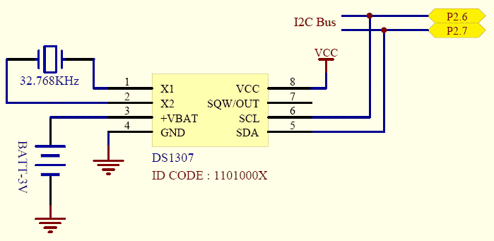
This is an example how to interface DS1307 with 8051. I use SDCC as C Compiler. My schematic is shown below.

Schematic: 8051 interface to DS1307

Datasheet
- DS1307 [pdf]

Source Code (For SDCC)
- ds1307.h
- test_ds1307.c

Note: require lcd.h and i2c.h


Related Links
- DS1307 Products Page
- Interfacing I2C RTC (DS1307) with MCS-51 (KEIL C51)

I²C Bus Interfacing

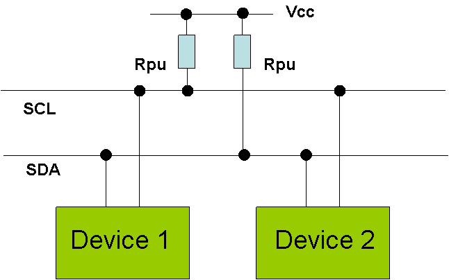
I²C bus (Inter-Integrated Circuit) is a bidirectional, half duplex, two-wire, synchoronous bus, originally designed for interconnection over short distances within a piece of equipment. The I2C bus uses two lines called Serial Clock Line (SCL) and Serial Data Lines (SDA). Both lines are pulled high via a resistor (Rpu) as shown in Figure below. The bus is defined by Philips, see more details.

Three speed modes are specified: Standard; 100kbps [Bits per Second], Fast mode; 400kbps, High speed mode 3.4Mbps. I2C, due to its two-wire nature (one clock, one data) can only communicate half-duplex. The maximum bus capacitance is 400pF, which sets the maximum number of devices on the bus and the maximum line length.

The interface uses 8 bit long bytes, MSB (Most Significant Bit) first, with each device having a unique address. Any device may be a Transmitter or Receiver, and a Master or Slave. The Slave is any device addressed by the Master. A system may have more than one Master, although only one may me active at any time.

Data and clock are sent from the Master: valid while the clock line is high. The link may have multiple Masters and Slaves on the bus, but only one Master may be active at any one time. Slaves may receive or transmit data to the master.

This is an example how to interface I²C with 8051. I use SDCC as C Compiler. My schematic is shown below. I set P2.6 as SCL and P2.7 as SDA.
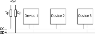
Schematic: I²C Bus

Datasheet
I²C-Bus Specification [pdf]

Source Code (For SDCC)
- i2c.h

Note: see DS1307 and 24LC512 for applications


Related Links
- Philips I²C Bus
- I2C (Inter-Integrated Circuit) Bus Technical Overview and Frequently Asked Questions (FAQ)
- I²C Bus and Access Bus
- http://www.i2c-bus.org/

Friday, September 8, 2006

Analog-to-Digital Interfacing


The ADS7841 is a 4-channel, 12-bit sampling Analog-to-Digital Converter (ADC) with a synchronous serial interface. The resolution is programmable to either 8 bits or 12 bits. It is a product of Burr-Brown form Texas Instrument, see the product page.

This ADC give the 12-bit Binary Code Decimal (BCD) output value therefore the maximum value is 999 integer. If we want to convert this value to the real value, we must divide this value by 4096 (12-bit) and multiply by the maximum real ouput. Suppose the real maximum of output is 5V, the ratio should be 5/4096 = 0.00122. We can use 0.00122 multiply the output from ADS7841 to get the real ouput value.

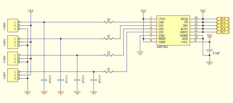
This is an example how to interface ADS7841 with 8051. I use SDCC as C Compiler. My schematic is shown below. I still do not convert to the real value so my variables are integer.

Schematic: 8051 interface to ADS7841

Datasheet
- ADS7841 [pdf]

Source Code (For SDCC)
- ads7841.h
- test_ads7841.c

Note: require lcd.h


Related Links
- ADS7841 Products Page

Thursday, September 7, 2006

LCD interfacing


This is an example how to interface to the standard Hitachi-44780 LCD using an 8051 microcontroller and SDCC as C Compiler. I use a standard 16-character by 2-line LCD module, see schematic below. Here, I use 4-bit interfacing.


Schematic: 4-bit interfacing 16x2 LCD

Source Code (For SDCC)
- lcd.h
- test_lcd.c


Related Links
- How to control a HD44780-based Character-LCD: The Industry Standard Character LCD
- Yet Another 8051-to-LCD Interface
- Interfacing: Converting 8-bit LCD communication to 4-bit